
Differences in Surface Profile Measurements: ASTM D4417- Method B vs. Method C
What is Surface Profile and Why is it Necessary?
Surface profile is defined as a measurement of the maximum peak-to-valley depth created by abrasive impingement against a surface during abrasive blast cleaning operations, or by an impact-type power tool. During abrasive blast cleaning, the mass of the abrasive and the velocity of the abrasive movement created by compressed air generates kinetic energy (the abrasive can reach speeds of over 600 miles per hour as it exits the blast nozzle). When the abrasive impacts the surface, it cuts into the surface (angular abrasives) or peens the surface (round abrasives) and creates a series of peaks and valleys in the surface.

The creation of this peak-valley pattern in the surface effectively increases the surface area, providing an anchor for the coating system. Both the structure and the coating system protecting the structure will move while in service. This movement may be caused by expansion and contraction of the substrate due to temperature fluctuation, or live loads placed onto a structure; for example, traffic crossing a bridge. The surface profile must be compatible with the coating system. Typically, the higher the coating thickness the greater the surface profile depth. Peak density (the number of peaks per unit area) also plays a key role in maintaining adhesion of the coating system and provides greater resistance to corrosion undercutting when the coating system gets damaged while in service.
Standards for Measurement of Surface Profile
There are currently four primary standards for measurement of surface profile in steel surfaces. Note that ASTM D4417 and SSPC-PA 17 also address measurement of surface profile generated by impact-type power tools. The four standards are:
- ASTM D4417, Standard Test Methods for Field Measurement of Surface Profile of Blast Cleaned Steel;
- ASTM D7127, Standard Test Method for Measurement of Surface Roughness of Abrasive Blast Cleaned Metal Surfaces Using a Portable Stylus Instrument;
- NACE SP0287, Field Measurement of Surface Profile of Abrasive Blast-Cleaned Steel Surfaces Using a Replica Tape; and
- SSPC-PA 17, Procedure for Determining Conformance to Steel Profile/Surface Roughness/Peak Count Requirements.
How is Surface Profile Depth Quantified?
ASTM D4417 contains three methods of measuring surface profile depth: Method A describes the proper use of a comparator; Method B describes the use of a depth micrometer, and Method C addresses the use of replica tape (as does NACE SP0287). Today, Method B and Method C are the most commonly used, so that is what we will be focusing on.
ASTM D4417, Method B
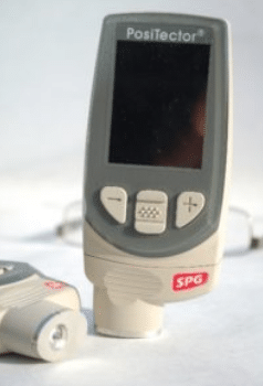
Method B in the ASTM standard describes the use of a depth micrometer. The surface profile depth micrometer measures the depth of the valleys of the surface profile relative to the height of the peaks using a 60° cone-shaped point protruding from the base of the gage. The base of the instrument rests on the peaks of the surface profile while the cone-shaped point projects into the valley. The depth is displayed on the gage in mils (0.001”) or micrometers (0.001mm; there are 25.4 micrometers [µm] in 1 mil). This method can be used to measure the surface profile depth that is created by abrasive blast cleaning or impact-type power tools. Models from a few gage manufacturers are available that conform to this standard.
According to ASTM D4417, a minimum of 10 readings is obtained per area; the maximum surface profile is reported (discarding obvious outliers). SSPC-PA 17 states that a minimum of three 6” x 6” areas are measured per work shift or 12 hours of preparation time, whichever is shorter. The measurements must conform to the minimum and maximum surface profile requirements listed in the project specification.
ASTM D4417, Method C

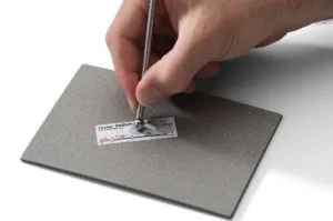
Method C in the ASTM standard describes the use of replica tape. A mirror image of the peak-valley pattern generated by abrasive blast cleaning is created in an emulsion foam applied to the underside of a 2-mil polyester film (Mylar®) by pressing the Mylar using a burnishing tool using medium pressure. Once the burnishing process is complete, the replica tape is removed from the surface and the image is measured using a spring-loaded micrometer.
The Mylar thickness (2 mils) is deducted from the measurement, revealing the depth of the surface profile within the measured area (approximately 3/8” diameter). Alternatively, a Replica Tape Reader (RTR) can be used to read the replica tape.

According to ASTM D4417, a minimum of 2 readings is obtained per area; the average of the two readings is reported. SSPC-PA 17 states that a minimum of three 6” x 6” areas are measured per work shift or 12 hours of preparation time, whichever is shorter. The measurements must conform to the minimum and maximum surface profile requirements listed in the project specification.
Same Surface, Different Results?
When a project specification simply invokes ASTM D4417 and not a specific method, the results of the surface profile measurements may differ when two different methods are used on the same project, even on the same surface and within the same area (i.e., the contractor’s quality control inspector is using replica tape and the facility owner’s quality assurance inspector is using the depth micrometer). While both the depth micrometer and replica tape methods conform to ASTM D4417, the measurement acquisition principles are quite different. The depth micrometer is measuring a single valley depth in relationship to potentially hundreds of “peaks” beneath the base of the instrument. Conversely, the replica tape image represents many peaks/valleys, and the micrometer is measuring a portion of those obtained (the test area on the replica tape is approximately 3/8” diameter and the anvils of the micrometer are approximately 1/8” in diameter). So, in effect the reading on the micrometer or the RTR from the replica tape represents several peaks and valleys, while the depth micrometer does not. Therefore, differences are inevitable, particularly with deeper surface profiles, and the results may or may not fall within the specified range for one of the two methods. To avoid these discrepancies, it is recommended that a single method be employed on a project. This can be discussed and agreed upon at the pre-construction conference.


Hi!
Thanks for your helpful and informative article!
Do you sell sample plates that can be used to train our people, or compare the relative performance of our various measurement tools? If not, will you please recommend one or more potential suppliers of those plates? ASTM D4417 Method B is our baseline standard.
Thanks!
John
Hi John! Yes, we do. Please contact us at sales@kta.com or call us at 1-800-582-4243 and we would be happy to assist you.