

What a Good Coatings Inspector Needs to Know
Written by William D. Corbett, COO
AMPP Senior Certified Coating Inspector & Certified Protective Coating Specialist
Introduction
The role of a Coatings Inspector has evolved, and the responsibilities have increased over what used to be a rather straightforward job: to verify that surface preparation and coating application performed by a contractor (or an in-house painting crew) conform to the minimum requirements of the project specification. Decades ago, equipped with the specification and some training on instrument use we set out to watch the contractor sandblast the surface, then mix, thin, and apply the paint (under acceptable conditions) to the correct thickness, then measure the thickness using a magnetic pull-off gage, and be done.
Today there are week-long or multi-week basic and advanced coating inspection training and certification courses; specialty courses that are industry-specific such as bridge, marine, and nuclear power; courses and certifications that are substrate-specific such as concrete coatings inspection; and even coating-specific inspection courses such as inspection of thermal spray coatings. In addition to coatings knowledge gained through course offerings available through associations and private industry, coatings inspectors may also need to be proficient in maintenance and protection of traffic, or worker exposure controls, monitoring of emissions, and waste management processes on hazardous paint removal projects. The value that a well-trained, competent coating inspector (with well-rounded knowledge of various surface preparation methods, coatings, specialty application methods, and industries) brings to a project cannot be overstated. Inspectors can help prevent or reduce rework that adversely impacts schedule and/or results in cost overruns and can help prevent premature coating failure.
Trained and certified coatings inspectors with competency in a variety of coatings, processes, and industries are often expected by the facility owners that hire the individual or the inspection firm. To fulfill this expectation, continuing education has become paramount to stay abreast of new standards and changes to existing ones, new instrumentation, and new coatings technology.
Do we now need a PhD in Coatings Inspection? Not exactly, but this white paper explores the role of a coating inspector as well as the basic skills of a competent coating inspector and the advanced skills that may be expected by facility owners. The goal is to present the roles, responsibilities, knowledge, skills, and attributes of a good coating inspector so that knowledge/experience gaps can be identified, and methods developed (through education, mentoring, and/or experience) to minimize or eliminate those gaps.
The Role and Requirements of a Coating Inspector

The role of a coating inspector is to Observe, Assess, Document and Report (OADR). That is, Observe the work that has been completed at the hold point, Assess whether the work completed meets the minimum requirements of the project specification, Document the results of the inspection, and Report (communicate) the outcomes to the facility/asset owner (for the role of QA inspector) or contractor management (for the role of QC inspector).

Further distinction is required however, in terms of defining the roles of a quality control (QC) inspector versus a quality assurance (QA) inspector. An article posted on KTA University titled,Roles & Responsibilities of Quality Assurance & Quality Control Personnel on a Coatings Project explores the differences. A QC inspector represents the painting contractor and is responsible for the frequent, routine, systematic inspections to verify each phase of the work meets the requirements set forth by the project specification. Since the painting contractor is ultimately responsible for providing quality workmanship and conforming to the specification, they are in fact controlling quality. Conversely, QA inspectors represent the facility/asset owner and may be part of the owner’s staff or be provided by a 3rd party. QA inspectors verify that quality is being controlled and that QC is being performed correctly and conducted at the frequency required by the specification. In many cases, QA inspectors provide the same level inspection as the QC inspector, but the responsibility for quality remains with the contractor and the QC inspector. If the QA inspector is an employee of the facility/asset owner then they have stop-work authority, whereas a 3rd party inspector working under contract to the facility/asset owner does not, since there is no contractual relationship between the 3rd party QA inspector and the contractor. Nonetheless, the “OADR” role does not seem all that complicated until one uncovers what all is involved.
In Chapter 2 of the SSPC publication, The Inspection of Coatings and Linings[1] the author describes the professional and personal requirements of coatings inspectors. It states that while the specific requirements will vary depending on the nature and purpose of the project, generally the requirements include physical ability, training, experience, written and verbal communication skills, and certain character traits. Ideally the inspector is prepared to respond to all quality issues that arise on a given project.

Physical Ability: Physical requirements of a coatings inspector often include the ability to climb, enter confined spaces, good vision (corrected as necessary) as well as the ability to distinguish colors, and manual dexterity. Climbing and entering confined spaces (as well as other conditions) will require proper use of personal protective equipment such as respirators, fall protection (harnesses and lanyards), and coveralls, which can be physically demanding, so an inspector should be physically fit and, when applicable, comfortable working from heights. Manual dexterity is required to properly use/manipulate inspection instruments that are becoming smaller and smaller for portability, which makes them more challenging to manipulate, especially while wearing gloves.

Training/Continuing Education: Formal training is a critical requirement for a coating inspector. Fortunately, there is no shortage of courses from trade organizations such as the Association for Materials Protection and Performance (AMPP) and FROSIO, as well as from private companies. These courses are frequently instructed by subject matter experts that have performed coating inspection for years, so they have lived and breathed the information conveyed throughout the course delivery. There are two essential components to inspector training: theory (visual/auditory learning) and hands-on (kinesthetic learning). One without the other is ineffective, which is challenging in today’s on-line/virtual microlearning environments that are expected by younger generations. There are frequently varying levels of training, from basic (introductory) to advanced, and there are now experience requirements before progressing from one level to the next.
However, initial training isn’t enough. Like most any occupation, continuing education is a critical component to a coating inspector’s value. Our world is changing exponentially, and the coatings industry is evolving rapidly. Coating specifications frequently reference industry standards that, once invoked by contract become contractual law. Industry standards change. In fact, most standards-writing organizations will review/revise/update their standards every 5-years or so, and new standards are published intermittently. So, without continuing education, a coating inspector that was trained on a specific inspection standard (e.g., coating thickness measurement) in year 2000 could easily be inspecting coating thickness according to a standard that has been revised/updated four times since they were initially trained.
In a technical paper titled, “Industry Standards: Are You Current?”[2] the author described why and how to remain current, then listed ten common coatings industry standards from SSPC, ASTM, NSBA and others that had been updated in the previous two years. Continuing education, particularly on industry standards, inspection techniques, instrumentation, and safety is a critical responsibility of a coatings inspector and a requirement of the AMPP-SSPC-QP 5 certification program[3]. While AMPP-SSPC-QP 5 certification is applicable to inspection companies and not individual inspectors, it does contain the physical requirements, duties, and the education, certification and experience requirements of coating inspectors that are worth reviewing by any coating inspector, not just those employed by the certified coating and lining inspection company.

Experience: Training without experience and experience without training can result in under- or over-inspection and poor quality. The point is that an inspector needs both to be of value to a facility/ asset owner. How often have we heard, “… now that you’ve completed your basic training hurry up and get 5 years of experience so we can get you to the next level?” Experience takes time, and there is both good and bad experience. In Chapter 2 of SSPC’s The Inspection of Coatings and Linings the author states that on-the-job training is best obtained by working under the supervision of an experienced inspector, and the supervising inspector should monitor the trainee’s work regularly to ensure that standard test procedures and practices are followed. This statement is accurate (and arguably the way the AMPP Coating Inspector Certification levels are intended), but it assumes the supervising inspector has the skills and attributes of a mentor and coach, and not just the technical knowledge. It also assumes project budgets can support two levels of inspectors. Nonetheless, experience is and should remain a requirement of a competent coating inspector, and a formal mentoring/coaching program (post-training) should be in the forefront of any certification program. But easier to say than to implement.
Verbal and Written Communication Skills: Another essential requirement of a competent coating inspector is the ability to clearly and concisely communicate both verbally and in writing. The information provided by an inspector must be professional and impartial. Patient, calm oral communication can be particularly challenging when issues arise (and tempers flare); however, the coating inspector should never be arrogant, rude, or excitable. Their role is to communicate the facts and if asked, offer comments on proposed options for corrective actions with the facility owner, specifier, and contractor superintendent.
Written communication is an art, and the ability to communicate using the written word should be a requirement of a competent inspector. Some will argue that written communication has become a lost art and that even the most educated individuals cannot convey their thoughts in a clear, concise, coherent manner. Despite that potential reality, written documentation is of critical importance on a coatings project and is a key element in resolving disputes or premature failure. While the coating specification reveals what was supposed to be done, an inspector’s documentation reveals what was done. Daily inspection reports contain data acquired using instruments, but a properly constructed narrative gives context to the data and provides the owner and the contractor management with a picture of how the project is progressing. As the demand for the use of electronic inspection reports increases, the importance of narrative is only heightened.
Responsibilities of a Coating Inspector

Once the role of a coating inspector is defined and the requirements to achieve and maintain coating inspector status are understood, the specific responsibilities of an inspector can be described. ASTM D3276[4] and ASTM D6237[5] are two common guides. According to their respective scopes, they are designed to aid painting inspectors in carrying out their tasks efficiently. They include the key elements of surface preparation, coatings application, and final approval for both field and shop work.
Common responsibilities of a coating inspector are listed in the Table 1. These responsibilities are generally, but not exclusively, related to inspection of coatings applied to steel; other responsibilities are added when coating concrete or other substrates. As clearly illustrated in the table, the responsibilities are numerous, but not all of them are necessary on a single project. Nonetheless, the competent coating inspector needs to be proficient in all responsibilities of all phases listed in the table. Interestingly, there are nine responsibilities before the project truly begins (“Pre-Project”). The inspection checkpoints denoted with a * are frequently contract specific.
Table 1: Common Coating Inspector Responsibilities by Project Phase
| Phase | Responsibility |
| Pre-Project | Read & comprehend the project specification; issue requests for clarification. Read and comprehend the coating manufacturer’s product data sheets (PDS); denote conflicts between the PDS and specifications and seek resolution. Read the Safety Data Sheets (SDS) for each hazardous product on the job and know the PPE required. Attend and participate in the Pre-construction Conference. Obtain a copy of the Pre-construction Conference minutes and note changes/clarifications to the project specification as appropriate and be current with all Addendums. Obtain pre-project safety training and/or required medical surveillance. Obtain PPE compatible with jobsite conditions/rules. Verify the type of inspection equipment required for the project; verify operation and accuracy as well as currency of calibration. Prepare an Inspection Plan, as required. |
| Materials Receipt/Storage | Verify materials such as cleaners, caulking, abrasive, coatings, thinners, etc. are received and stored correctly. Verify the shelf life of materials has not expired. Record batch numbers of components and thinners. Monitor storage areas for temperature & humidity*. Document all information. |
| Pre-Surface Preparation | Verify removal of visible grease/oil, etc. per SSPC-SP 1 Inspect edges, welds, fasteners for coat-ability; verify spatter and lamination removal; inspection of section loss*. Examine the structure for difficult-to-access areas and bring them to the attention of the owner for resolution (if not already addressed by the specification). Conduct surface soluble salt contamination testing (may also be required post-preparation) *. Verify compatibility of surface preparation equipment and expendables (e.g., abrasive) with the specification requirements. Verify protective covering are in place and secure. Verify proper lighting*.Document all information. |
| Surface Preparation | Measure ambient conditions and surface temperature prior to final surface preparation. Inspect indirect requirements of SSPC abrasive blast standards. Compressed air cleanliness. Abrasive cleanliness (water-soluble contaminants & oil). Determine initial condition of the steel (Rust grade).Inspect surface cleanliness per level specified. Inspect surface profile depth (and peak density*). Inspect for adequate removal of soluble salts when required after preparation*. Verify adequate dust removal. Verify maximum preparation-to-primer time not exceeded. Document all information. |
| Mixing/Thinning | Measure ambient conditions and surface temperature. Verify coating components being mixed are correct. Measure coating material temperature. Verify correct proportions if mixing of partial kits is allowed. Verify proper mixing procedures per PDS. Verify proper type and amount of thinner, if used. Verify induction time per PDS. Verify mix is applied prior to pot life expiration. Document all information. |
| Coating Application | Verify compatibility of coating application equipment with the PDS. Measure ambient conditions and surface temperature throughout application at intervals required. Verify stripe coating*. Verify the wet film thickness (WFT) target has been adjusted for thinner amounts added and that applicators are using WFT gages. Verify recoat times (minimum/maximum). Verify intercoat cleanliness and watch for amine exudate formation for certain types of epoxy coatings. Document all information. |
| Post-Coating Application | Measure dry film thickness of each coat. Perform pinhole/holiday detection*. Perform hardness/cure testing*. Perform adhesion testing*. Document all information. |
| Other (project/role-dependent) | Inspecting duplex coating systems. Verify proper primer application and curing time to faying surfaces of slip-critical connections (per Test —-Certificate/Essential Variables). Verify compliance with OSHA worker lead exposure requirements. Verify containment structure “as built” meets design criteria. Verify ventilation inside containment. Verify protection of air, soil, water, and public adjacent to the worksite, including associated monitoring. Verify waste is segregated, stored, and transported properly. Verify acceptability of site housekeeping. |
Knowledge, Skills, and Attributes
Roles and responsibilities are related to, but different than knowledge, skills, and attributes, or KSAs of a competent coating inspector. For coating inspectors to perform their duties competently they must have the knowledge of industry standards and instrument use, as well as the ability to apply that knowledge to project-specific situations that invariably crop up on nearly every project. The ability to assess a situation, tap into learned knowledge, industry standards, and common sense, and apply that knowledge to help resolve problems as they occur is arguably one of the most valuable and sought-after attributes of a coating inspector. This comes with experience. For a QA inspector it also presents itself as a fine line between helping to resolve issues and directing the work. That too comes with experience.
Knowledge of Industry Standards: As previously described, most coating specifications reference industry standards (e.g., SSPC-SP 10, Near-White Abrasive Blast Cleaning, SSPC-PA 2, Procedure for Determining Conformance to Dry Coating Thickness Requirements, etc.) And many standards reference other standards. Coating inspectors must know the direct and indirect requirements of industry standards as well as the referenced standards within them. For example, for abrasive blast cleaning, they must know how much, if any, staining can remain on the surface (and how it is evaluated), differences between rust back and staining, what qualifies as a dull putty knife as an inspection tool, use of visual aids, how many surface profile readings to acquire in a location and how many locations to measure, requirements for testing the cleanliness of the compressed air, and how to determine specification conformance based on the data acquired. In the case of coating thickness, the measurements themselves are easy. Acquiring coating thickness data at the correct frequency and processing the data to determine acceptability is the difficult part of inspection.
Further, these standards change over time and new standards are developed. It can become a full-time job simply keeping up with industry standards. But knowingly or unknowingly performing inspections that conflict with the referenced standards can be problematic and even potentially lead to litigation. Access to current industry standards is critical for the inspector. It is just as important as the instruments used to perform the inspections.=
Knowledge of Instrument Use: The successful performance of a protective coating system depends on the quality of the surface preparation and coating system installation. To verify quality and specification compliance, inspectors rely heavily on data generated by inspection instruments and on visual inspections of the prepared and coated surfaces. Without proficiency in instrument use and an understanding of how to navigate through SSPC visual guides, it is nearly impossible to determine specification compliance. That is, you can’t tell how thick the paint is unless you measure it. You don’t know if the measurement is right if you don’t know how to use the gage. The publication, Using Coating Inspection Instruments[6], was written to assist inspectors, contractors, facility owners, engineers, coating manufacturers and other coating professionals with the proper use of inspection instruments, guides, and test kits. Many standards reference instrument manufacturer’s instructions for proper use; however, if there are differences between the manufacturer’s instructions and an industry standard, the inspector should obtain clarification prior to project start-up.
Many of the inspection checkpoints listed in Table 1 require the use of instruments, visual guides, or test kits, and new instrumentation routinely comes to the marketplace to fill a void, such as abrasive cleanliness test kits. Proficient use of instruments, guides, and test kits remains a critical function of a competent coating inspector. But instrument use is only part of the equation. A competent inspector must also understand the importance and frequency of calibration (and who is accredited to perform calibration) and the procedures for routine verification of instrument accuracy. Use of uncalibrated inspection instruments is considered by AMPP to be a malpractice ethics violation for a certified inspector.
Character Traits: Imagine if coating inspectors were like fast food chain hamburgers… no matter what, they would all be essentially the same consistency and quality. Knowledge, skills, and attributes of inspectors would be equal, and enforcement of the project specification would be completely uniform. What we are describing is an inspector that is devoid of a personality. As long as coating inspection is performed by humans, we have to consider how personality and character traits play a role. That is, knowledge, skills, and attributes of inspectors will not be equal, and enforcement of the project specification won’t be completely uniform, despite how important these items are to a facility/asset owner and contractor. Personality types and traits is a well-published topic, so the focus herein will be on ethics and judgement.
As the author states in Chapter 2 of The Inspection of Coatings and Linings, a coating inspector must have high personal integrity and a strong work ethic to enforce the specification without personal bias. Frequently an analogy is made between the role of a coating inspector and a police officer: enforce the law without personal bias. Like a police officer, a coating inspector does not write the law (the specification) but is charged with enforcing it without imposing personal standards of quality or workmanship. An inspector must remain constantly aware that the criteria for work acceptance is established by the project specification and not their personal viewpoint as to what will provide the best performance, what the specifier meant, or what will work best. Making concessions to maintain or improve the project schedule is never the role of an inspector. Even the most comprehensive, well-written specification cannot address every possible problem/challenge that may arise on a project, so some knowledge-based judgement on the part of the contractor, inspector, and owner will occasionally be required. However, the role of the inspector is not to interpret or modify the specifications without the knowledge of the owner.
One should never lose sight that the facility/asset owner, contractor, and coating inspector share a common goal: Provide long term corrosion protection of the structure or asset. Working together to execute the specification should be the mantra. The relationship between the contractor and inspector needn’t be adversarial if each understands the common goal and the pathway to achieve that goal.
Summary
The value that a well-trained, competent coating inspector brings to a project cannot be overstated. Inspectors can help prevent or reduce rework that adversely impacts schedule and/or results in cost overruns and can help prevent premature coating failure. Initial training, coaching/ mentoring, continuing education, experience, and both verbal and written communication skills are all key to a competent coating inspector. Complete, thorough knowledge of industry standards and instrument use combined with high personal integrity and a strong work ethic to enforce the specification without personal bias are equally important. When all these KSAs of a competent coating inspector are brought to bear on a coatings project they can help to achieve the common goal: long term corrosion protection of the asset or facility.
| Instrument | Purpose | Reference Standard(s) |
| Air & Dew Point Temperature Meter; Relative Humidity Meter | Measure prevailing ambient conditions prior to final surface preparation, prior to coating mixing, and during coating application | ASTM E337 |
| Surface Temperature Thermometer | Verify the surface temperature is a minimum of 5°F higher than the dew point temperature (and rising) | SSPC- PA 1 |
| Rotating Vane Anemometer | Determine conformance to minimum air flow (ventilation) requirements inside containment | SSPC Guide 6 |
| Light Meter | Determine conformance to minimum illumination requirements for the work area as well as surface preparation/coating application and inspection operations | SSPC Guide 12 |
| Abrasive Contamination Test Kit | Determine conformance to maximum water-soluble contaminant levels on new and reused abrasive | SSPC Abrasive Standards AB 1, AB 2, AB 3, AB 4 |
| Blast Nozzle Orifice Gage | Monitor blast nozzle wear | NA |
| Hypodermic Needle Pressure Gage | Monitor minimum blast nozzle pressure | NA |
| Blotter Paper | Verify compressed air does not contain visible oil or water | ASTM D4285 |
| Spring Micrometer or Replica Tape Reader with Replica Tape | Measure the resulting surface profile depth after abrasive blast cleaning | ASTM D4417, Method C |
| Depth Micrometer | Measure the resulting surface profile depth after power tool and/or abrasive blast cleaning | ASTM D4417, Method B; SSPC-SP 15; SSPC-SP 11 |
| Surface Contamination Analysis Test (SCAT) Kit | Verify surface salt contamination levels do not exceed acceptable levels, per specification | Per Project Specification |
| SSPC Visual (VIS) Guides | Aid in assessing surface cleanliness | SSPC Surface Preparation Standards |
| Dull Putty Knife | Aid in determining loosely versus tightly adhering materials | SSPC Surface Preparation Standards |
| Wet Film Thickness Gage | Determine the speed and number of spray passes to achieve to correct film build | ASTM D4414 |
| Dry Film Thickness Gage | Determine the thickness of individual coating layers | SSPC-PA 2 |
| Certified Coated Standards | Verify the accuracy of a dry film thickness gage | ASTM D7091; SSPC-PA 2 |
| Wall Thickness Gage | Determine section loss of a material like steel | NA |
| Inspection Mirror | Aid with visual inspection of difficult access areas | NA |
| Low Voltage Pinhole Detector | Detect pinholes/discontinuities in a lining system | ASTM D5162 |
| Tape/Knife Adhesion Test Kit | Assess the adhesive/cohesive properties and a coating system | ASTM D3359; D6677 |
| Hardness Tester | Determine the cure of a coating prior to service | ASTM D2240 |
[1] The Inspection of Coatings and Linings, SSPC: The Society for Protective Coatings Publication 97-07, Chapter 2, Inspection Personnel, Kenneth B. Tator
[2] W.D. Corbett (2016). Industry Standards: Are You Current? Proceedings of the SSPC National Conference and Exhibition, 2016.
[3] AMPP-SSPC Qualification Procedure No. 5, Standard Procedure for Evaluating the Qualifications of Coating and Lining Inspection Companies, AMPP: Association for Materials Protection & Performance.
[4] ASTM D3276 Standard Guide for Painting Inspectors (Metal Substrates), Volume 06.01, ASTM International, Conshohocken, PA USA
[5] ASTM D6237, Standard Guide for Painting Inspectors (Concrete and Masonry Substrates), Volume 06.01, ASTM International, Conshohocken, PA USA
[6] Using Coatings Inspection Instruments, 3rd Edition (2012), W.D. Corbett, KTA-Tator, Inc., Pittsburgh, PA USA

Watch Our Free Surface Profile Webinar
Click on the image below to register for one of the open slots for this free webinar featuring KTA Chief Operations Officer, Bill Corbett. When you click, you’ll be redirected to a page with full details of the presentation.

Measuring Peak Density Using Optical Grade Replica Tape
Introduction
Most industrial and marine protective coatings rely on a mechanical bond to the substrate to remain attached while in service. This bond is generally provided by a surface profile or anchor pattern that is imparted into the surface prior to application of the coating system and effectively increases the surface area of the substrate (e.g., steel). A surface profile is typically generated by abrasive blast cleaning; although some types of rotary impact-type power tools can also create a surface texture. Without this mechanical “tooth” the coating system may become detached as the substrate and coating system expand and contract (e.g., due to temperature fluctuations and/or service loading/unloading) while in service, Coating specifications frequently invoke a minimum and maximum surface profile depth (e.g., 2-4 mils), but rarely invoke a minimum peak count or peak density.
The Significance of Peak Density
While surface profile depth is important, the number of peaks per unit area is also a significant factor that can improve long term coating system performance. According to a study conducted in the early 2000’s[1] a high peak count characteristic of surface profile helps resist undercutting corrosion when the coating system becomes damaged while in service, and provides the coating system with better adhesion to the prepared substrate. More recent research conducted by the DeFelsko Corporation[2] confirmed that a greater peak density (pd) promotes coating system adhesion. So, while there is typically a maximum peak height invoked by a specification (to prevent pinpoint rusting resulting from unprotected rogue peaks), there is little concern over too many peaks. The more peaks there are within a given area, the greater the surface area; the greater the surface area, the better the adhesion. Note that this is the primary reason why thermal spray coatings (metallizing) cannot be applied to steel surfaces prepared with steel shot. While the surface profile depth may be adequate (i.e., 3-4 mils), the peak density of a peened surface will not provide the necessary surface area for proper adhesion, and disbonding will likely occur.
Peak Density Verses Peak Count
Peak density and peak count are similar, but slightly different in how they are reported. According to ASTM, relative peak count or rpc is defined as, “the number of peak/valley pairs, per unit of length, extending outside a “deadband” centered on the mean line,” and is typically reported in peaks/cm. Peak density (pd) is the number of peaks present within a given surface area, and is typically reported in peaks/mm2.
Governing Industry Standards
Surface profile or anchor pattern is quantified/semi-quantified according to one of the three methods described (comparator, depth micrometer, replica tape) in ASTM D4417, Standard Test Methods for Field Measurement of Surface Profile of Blast Cleaned Steel, and peak count is quantified according to the method described in ASTM D7127, Standard Test Method for Measurement of Surface Roughness of Abrasive Blast Cleaned Metal Surfaces Using a Portable Stylus Instrument. The frequency and acceptability of the acquired measurements is described in SSPC-PA 17, Procedure for Determining Conformance to Steel Profile/Surface Roughness/Peak Count Requirements.
Quantifying Peak Count and Peak Density
Peak count is quantified using a portable stylus-type instrument. According to ASTM D7127, the apparatus consists of a portable skidded or non-skidded electronic surface roughness measurement instrument capable of measuring Rpc in compliance with ASME B46.1. The apparatus should have a vertical range of at least 300 μm and permit a sampling length of 2.5 mm and an evaluation length of 12.5 mm. The apparatus should include a stylus with a tip radius of 5 μm, and permit recording of Rpc up to 180/cm. Surface deviations are sensed by the stylus and converted to electrical signals within the device. Internal processing converts these signals into standard surface characterization parameters, which are then displayed or printed. ASTM D7127 recommends obtaining a minimum of five (5) traces per area to characterize the surface. Many of the stylus-type instruments that will measure peak count were designed for manufacturing and/or the machine finishing industry rather than for field use. When used in the field, extreme care is necessary as the tip of the stylus can easily be damaged.
Peak density can be quantified using replica tape; however, this procedure requires the use of a slightly different version of the tape (called Optical Grade) than is traditionally used to measure surface profile depth per ASTM D4417, Method C (Coarse, X-Coarse and X-Coarse Plus). While the burnishing procedures are the same, the type of tape and the way that the tape is read differs. Both peak height and peak density are measured and reported using the Optical Grade replica tape and a Replica Tape Reader (RTR). ASTM recommends obtaining two measurements per area to characterize the surface.
Use of Optical Grade Replica Tape to Determine Peak Density

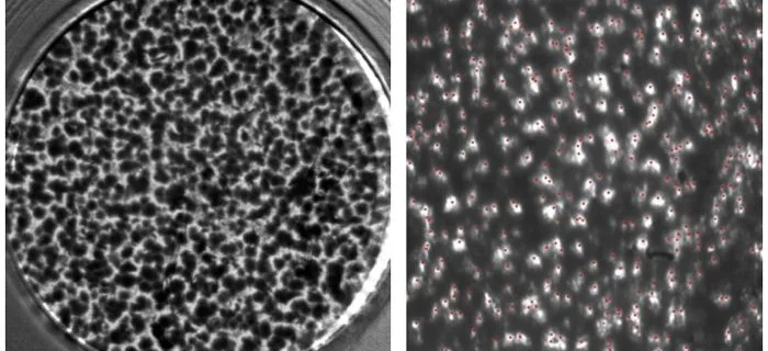
The model RTR-P incorporates a digital camera and light source. Light is passed through the replica tape and imaged by the camera. Peak counts are revealed as bright spots on the photograph as taken by the PosiTector RTR’s digital image sensor (camera). The intensity of light that passes through the replica tape is inversely proportional to the thickness of the compressed foam. The below photographs of a back-lit piece of replica tape reveals light areas of higher compression (peaks) and dark areas of lower compression (valleys). An illustration using an image from a US coin is also provided below that demonstrates how the camera distinguishes higher and lower compression areas. All images are courtesy of DeFelsko Corporation.

Illustration of Optical Grade Tape using image from US coin
Since peak density can now be readily measured in the field (and measured simultaneously with peak height using the same replica tape), it is likely that specifications will start requiring measurements of peak density, especially for materials such as metallizing that rely on mechanical bonding. Not so fast… simply requiring the measurement of peak density will accomplish little without establishing a minimum acceptance criteria, just as specifying the measurement of coating thickness without an acceptable range is of little value. The minimum required peak density for proper bonding of the coating system will need to be established, and will likely vary depending on the coating system. In addition, the steps required to increase peak density without adversely affecting peak height will also need to be investigated.
[1] The Effect of Peak Count of Surface Roughness on Coating Performance; Hugh J. Roper, Raymond E.F. Weaver, Joseph H. Brandon; Journal of Protective Coatings & Linings, Volume 21, No. 6; June 2005
[2] Replica Tape – Unlocking Hidden Information; David Beamish; Journal of Protective Coatings & Linings, Volume 31, No. 7; July 2015


Surface Soluble Salt Measurement – Conductivity Verses Ion-specific Methods of Analysis
Chemical contaminants on a surface can include chlorides, ferrous ions, sulfates and nitrates, among other types of soluble salts. Chloride may come from deicing materials or marine/coastal environments, ferrous ions are a by-product of corrosion, sulfates can be airborne, particularly in industrial environments (e.g., coal-fired power plants) and nitrates may come from the soil (e.g., fertilizers). These chemicals are deposited onto surfaces while the structure is in service, or during transportation of new steel to the fabrication shop, or from the shop to the field. They can typically be removed from surfaces by pressure washing or water jetting using clean water or water with the addition of a proprietary salt removal-enhancing solution. The effectiveness of the pressure washing step is dependent on the condition of the surface. That is, contamination is relatively easy to remove from smooth surfaces, but may be more challenging if the surfaces are pitted or are configured with difficult-access areas, as contamination will tend to concentrate and become trapped in these areas. If the salts are not detected or are not adequately dissolved and rinsed from the surfaces, they can become trapped beneath a newly-installed coating system. Provided there is a sufficient quantity of water in the service environment, and the concentration of the water-soluble contaminant trapped beneath the coating system is high enough, water can be drawn through the coating film by a process known as “osmosis.” This drawing force can be quite powerful, and will continue until the concentration of salt in water is the same on both sides of the coating film (the concentration reaches equilibrium). This process creates a build-up of water and pressure beneath the coating film, oftentimes enough to cause blistering of the coating (known as osmotic blistering), underfilm corrosion and premature coating failure.
It is for these reasons that many specifications require inspection of surfaces for chemical contaminants after surface preparation operations are complete, but before application of the primer. Because this type of contamination cannot be detected visually, the surface must be sampled and the “surface extraction” tested for the contaminant(s) of concern. SSPC Guide 15, “Field Methods for Retrieval and Analysis of Soluble Salts on Steel and Other Nonporous Surfaces” describes common methods for sampling and analysis of soluble salt contamination, with the intent of assisting the user in selecting an extraction and analysis procedure. Guide 15 is contained in Volume 2 of the SSPC Steel Structures Painting Manual, “Systems and Specifications.” A copy of the Guide is available from SSPC (www.sspc.org).

Common methods of extracting soluble salts from surfaces for analysis include: surface swabbing; latex patches/cells (ISO 8502, Part 6) and latex sleeves. Common methods of analysis of the extracted soluble salts include ion-specific test strips/tubes for chloride, ferrous ion and nitrate salts; drop titration for chloride; and turbidity meters for sulfate ion detection. Each of these methods of analysis are considered “ion-specific.”

Except when chemical additives are employed, the methods of reducing the surface concentrations (i.e., pressure washing [low or high pressure], steam cleaning or other methods) are not ion-specific. So consideration may be given to performing the analysis of the extracted solution using a non-ion specific method of analysis known as conductivity (ISO 8502, Part 9), rather than conducting multiple ion-specific tests on the extracted sample(s), since the method of removal typically addresses all soluble salts. In this case, a sample is extracted from the surface using any of the methods listed above (swab, latex or latex patch) using distilled or deionized water. Once the extraction is complete, the solution is placed directly onto a conductivity meter (verified for accuracy first; see below) that will accommodate small samples and that automatically compensates for the temperature of the liquid (temperature compensation is very important for the proper use of conductivity meters).
The conductivity meter displays the concentration of the ionic contamination in millisiemens/cm (mS/cm) or microsiemens/cm (µS/cm). To convert from mS/cm to µS/cm, multiply mS/cm by 1000 (e.g., 0.35 mS/cm is 350 µS/cm). Note that for the values from the conductivity meter to have any meaning, the area of the surface being sampled and the volume of water used in the extraction must also be known, which will be the case when using the sampling methods listed above, particularly ISO 8502, Part 6 and Part 9. The conductivity meter will not reveal the type of ionic contamination; that is, it will remain unknown whether the conductivity reading is due to chloride, ferrous ion, nitrate, sulfate or other soluble salts. All that is known is that there is ionic contamination in the extracted test sample. Naturally the conductivity of the extraction solution (the distilled or deionized water) should be tested (known as a “blank”) and any conductivity reading of the water deducted from the reading of the surface extraction sample(s). For example, if the conductivity of the surface extraction is 354 µS/cm and the conductivity of the distilled/deionized water is 3 µS/cm, the reported conductivity is 351 µS/cm.
Many specifications have established thresholds for the maximum amounts of surface salt contamination based on the type of salt (e.g., 7 µg/cm2 chloride; 10 µg/cm2 nitrate and 17 µg/cm2 sulfate). If conductivity testing is substituted for ion-specific testing, then the specifier will need to establish thresholds based on conductivity values (in µS/cm). For example, the US Navy has established thresholds of 70 µS/cm for atmospheric (non-critical) service and 30 µS/cm for immersion (critical) service.

There can be considerable cost savings associated with changing from ion-specific testing to conductivity measurements, since each ionic contaminant of interest must be analyzed using different methods. And none of the kits contain re-usable supplies, so contractors must purchase many kits for each project. Naturally these costs are passed on to the owner, as part of the contractor’s bid. By performing conductivity instead of ion-specific analyses, the costs are reduced since the conductivity meter can be used for thousands of readings, as long as it remains accurate and within the manufacturer’s tolerance. Most of the portable conductivity meters come with a standard solution (known as a buffer solution) with a known conductivity for verifying the accuracy of the meter. Verification of accuracy before each use is recommended.
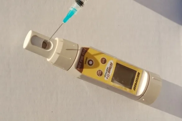
Finally, it is worth mentioning that there are a few devices on the market that perform both extraction and analysis of the surface, and display the surface salt concentrations in PPM, mS/cm, µS/cm or µg/cm2. Similar to the conductivity meter these instruments are not ion-specific, but are typically more costly than a portable conductivity meter. They do not use any expendable supplies (other than distilled water) and they too compensate for temperature.


Differences in Surface Profile Measurements: ASTM D4417- Method B vs. Method C
What is Surface Profile and Why is it Necessary?
Surface profile is defined as a measurement of the maximum peak-to-valley depth created by abrasive impingement against a surface during abrasive blast cleaning operations, or by an impact-type power tool. During abrasive blast cleaning, the mass of the abrasive and the velocity of the abrasive movement created by compressed air generates kinetic energy (the abrasive can reach speeds of over 600 miles per hour as it exits the blast nozzle). When the abrasive impacts the surface, it cuts into the surface (angular abrasives) or peens the surface (round abrasives) and creates a series of peaks and valleys in the surface.

The creation of this peak-valley pattern in the surface effectively increases the surface area, providing an anchor for the coating system. Both the structure and the coating system protecting the structure will move while in service. This movement may be caused by expansion and contraction of the substrate due to temperature fluctuation, or live loads placed onto a structure; for example, traffic crossing a bridge. The surface profile must be compatible with the coating system. Typically, the higher the coating thickness the greater the surface profile depth. Peak density (the number of peaks per unit area) also plays a key role in maintaining adhesion of the coating system and provides greater resistance to corrosion undercutting when the coating system gets damaged while in service.
Standards for Measurement of Surface Profile
There are currently four primary standards for measurement of surface profile in steel surfaces. Note that ASTM D4417 and SSPC-PA 17 also address measurement of surface profile generated by impact-type power tools. The four standards are:
- ASTM D4417, Standard Test Methods for Field Measurement of Surface Profile of Blast Cleaned Steel;
- ASTM D7127, Standard Test Method for Measurement of Surface Roughness of Abrasive Blast Cleaned Metal Surfaces Using a Portable Stylus Instrument;
- NACE SP0287, Field Measurement of Surface Profile of Abrasive Blast-Cleaned Steel Surfaces Using a Replica Tape; and
- SSPC-PA 17, Procedure for Determining Conformance to Steel Profile/Surface Roughness/Peak Count Requirements.
How is Surface Profile Depth Quantified?
ASTM D4417 contains three methods of measuring surface profile depth: Method A describes the proper use of a comparator; Method B describes the use of a depth micrometer, and Method C addresses the use of replica tape (as does NACE SP0287). Today, Method B and Method C are the most commonly used, so that is what we will be focusing on.
ASTM D4417, Method B
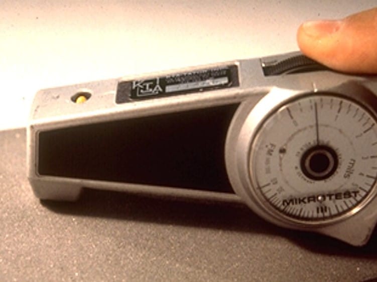
Method B in the ASTM standard describes the use of a depth micrometer. The surface profile depth micrometer measures the depth of the valleys of the surface profile relative to the height of the peaks using a 60° cone-shaped point protruding from the base of the gage. The base of the instrument rests on the peaks of the surface profile while the cone-shaped point projects into the valley. The depth is displayed on the gage in mils (0.001”) or micrometers (0.001mm; there are 25.4 micrometers [µm] in 1 mil). This method can be used to measure the surface profile depth that is created by abrasive blast cleaning or impact-type power tools. Models from a few gage manufacturers are available that conform to this standard.
According to ASTM D4417, a minimum of 10 readings is obtained per area; the maximum surface profile is reported (discarding obvious outliers). SSPC-PA 17 states that a minimum of three 6” x 6” areas are measured per work shift or 12 hours of preparation time, whichever is shorter. The measurements must conform to the minimum and maximum surface profile requirements listed in the project specification.
ASTM D4417, Method C

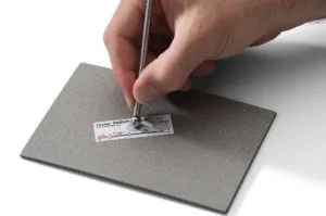
Method C in the ASTM standard describes the use of replica tape. A mirror image of the peak-valley pattern generated by abrasive blast cleaning is created in an emulsion foam applied to the underside of a 2-mil polyester film (Mylar®) by pressing the Mylar using a burnishing tool using medium pressure. Once the burnishing process is complete, the replica tape is removed from the surface and the image is measured using a spring-loaded micrometer.
The Mylar thickness (2 mils) is deducted from the measurement, revealing the depth of the surface profile within the measured area (approximately 3/8” diameter). Alternatively, a Replica Tape Reader (RTR) can be used to read the replica tape.

According to ASTM D4417, a minimum of 2 readings is obtained per area; the average of the two readings is reported. SSPC-PA 17 states that a minimum of three 6” x 6” areas are measured per work shift or 12 hours of preparation time, whichever is shorter. The measurements must conform to the minimum and maximum surface profile requirements listed in the project specification.
Same Surface, Different Results?
When a project specification simply invokes ASTM D4417 and not a specific method, the results of the surface profile measurements may differ when two different methods are used on the same project, even on the same surface and within the same area (i.e., the contractor’s quality control inspector is using replica tape and the facility owner’s quality assurance inspector is using the depth micrometer). While both the depth micrometer and replica tape methods conform to ASTM D4417, the measurement acquisition principles are quite different. The depth micrometer is measuring a single valley depth in relationship to potentially hundreds of “peaks” beneath the base of the instrument. Conversely, the replica tape image represents many peaks/valleys, and the micrometer is measuring a portion of those obtained (the test area on the replica tape is approximately 3/8” diameter and the anvils of the micrometer are approximately 1/8” in diameter). So, in effect the reading on the micrometer or the RTR from the replica tape represents several peaks and valleys, while the depth micrometer does not. Therefore, differences are inevitable, particularly with deeper surface profiles, and the results may or may not fall within the specified range for one of the two methods. To avoid these discrepancies, it is recommended that a single method be employed on a project. This can be discussed and agreed upon at the pre-construction conference.


What is a Base Metal Reading and How Does It Effect Coating Thickness Measurements?
For many in the health care/fitness industry, BMR is an acronym for basal metabolic rate. Sorry to disappoint if you thought this would be a health science article about expending energy. Rather, this article is about a different BMR: Base Metal Reading. We’ll describe what it is, its significance, how to obtain it, and how it impacts coating thickness.
Introduction to Coating Thickness Standards
There are two common industry standards that govern measurement of coating dry film thickness on metal substrates, including ASTM D7091, Standard Practice for Nondestructive Measurement of Dry Film Thickness of Nonmagnetic Coatings Applied to Ferrous Metals and Nonmagnetic, Nonconductive Coatings Applied to Non-Ferrous Metals and SSPC-PA 2, Procedure for Determining Conformance to Dry Coating Thickness Requirements. Both address the use of Type 1 (magnetic pull-off) and Type 2 (electronic) gages as well BMR acquisition. SSPC-PA 2 also addresses measurement frequency and the acceptability of the measurements.
What is BMR?

BMR is the effect of substrate roughness on a coating thickness gage. The roughness is created by preparation of the substrate (e.g., abrasive blast cleaning or power tool cleaning), which generates a surface texture or “profile,” or by a manufacturing process that imparts roughness into the substrate. Instruments that measure the dry film thickness of the applied coating reach part way down into the roughened metal surface to operate properly (illustrated by the red line). However, specifications list the required coating thickness as measured from the tops of the peaks of the surface profile (illustrated by the blue bar). This inherent delta is known as the base metal effect. It is deducted from the coating thickness measurements to eliminate any effect of surface roughness. If the BMR is ignored, the thickness of the coating from the tops of the peaks of the surface profile may be overstated.

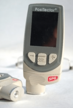
Acquisition of a BMR is not predicated on the gage type (Type 1 magnetic pull-off verses Type 2 electronic), but rather the way the gage is set-up by the operator to compensate for surface roughness. For both Type 1 (see photo, left) and Type 2 gages a BMR may be acquired and deducted from the coating thickness.

As an alternative, for Type 2 gages one or more measured shims (one shim is considered a one-point adjustment while the use of two shims spanning the range of intended use is considered a two-point adjustment) may be placed onto the prepared (roughened) metal surface and the gage adjusted to correspond to the shim thickness, effectively removing any need to measure and deduct a BMR. According to SSPC-PA 2, these measured shims are not permitted to be used with Type 1 gages unless explicitly allowed by the gage manufacturer, so in most cases a BMR will be required when using a Type 1 gage.
Obtaining Base Metal Readings
Section 6.2 in SSPC-PA 2 states, “To compensate for any effect of the substrate itself and surface roughness, obtain measurements from the bare, prepared substrate at a minimum of ten locations (arbitrarily spaced) and calculate the average value. This average value is the base metal reading.” Here are the steps:
- Verify the accuracy of the coating thickness gage before use. Traceable coated standards are required for both Type 1 and Type 2 coating thickness gages.
- Obtain a minimum of ten readings on the prepared, uncoated substrate in random locations. To avoid forgetting to acquire a BMR, it is best to take the measurements at the same time surface profile measurements are obtained.
- Measure the coating thickness.
- Deduct the average BMR.
The BMR is not only deducted from the primer thickness, but the cumulative layer thickness measurements as they are obtained. This is illustrated below:
Measured primer thickness: ———————————————————- 4.9 mils
BMR: ———————————————————————————— (0.6 mil)
Actual primer thickness from the top of the peaks of the surface profile: —— 4.3 mils
Cumulative primer & topcoat thickness: ——————————————— 9.2 mils
BMR: ————————————————————————————- (0.6 mil)
Actual cumulative thickness from the top of the peaks of the surface profile: — 8.6 mils
It is important to recognize that BMR and surface profile are related, but they are not the same. Surface profile is a measurement of the maximum peak-to-valley depth created by abrasive blast cleaning or some type of impact power tool. It is measured using one of three methods described in ASTM D4417, Standard Test Methods for Field Measurement of Surface Profile of Blast Cleaned Steel and SSPC-PA 17, Procedure for Determining Conformance to Steel Profile/Surface Roughness/Peak Count Requirements. BMR is the effect of this surface profile on a coating thickness gage. A 3-mil surface profile may have an associated BMR of 0.7 mil. Deducting surface profile from the coating thickness instead of the BMR will result in a significant under-recognition of the actual coating thickness.


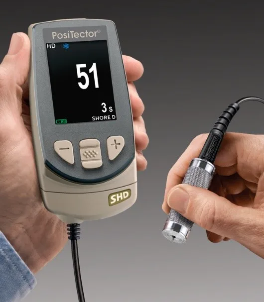
Using Scanning Probe Technology to Measure Coating Thickness
Introduction
Coating thickness measurement is one of the most common quality assessments made during industrial coating applications. SSPC-PA 2, Procedure for Determining Conformance to Dry Coating Thickness Requirements is frequently referenced in coating specifications. As SSPC-PA 2 has evolved over the past four decades, a number of procedures and measurement frequencies are referenced in both the mandatory portions of the standard and in the non-mandatory appendices. While the measurement frequencies were never intended to be a statistical process, it is helpful to understand the statistical implications of the measurement process. And it is helpful to know what coating thickness variability is reasonable. This brief article explores how scanning probe technology can help to acquire a larger number of measurements (in a relatively short period of time) to better assess the consistency of the applied coating thickness, particularly on larger, more complex structures.
Background

Scanning Illustration, courtesy of Elcometer Ltd.
There are two industry standards that are widely specified for measurement of coating thickness. These include ASTM D7091, Standard Practice for Nondestructive Measurement of Dry Film Thickness of Nonmagnetic Coatings Applied to Ferrous Metals and Nonmagnetic, Nonconductive Coatings Applied to Non-Ferrous Metals and SSPC-PA 2, Procedure for Determining Conformance to Dry Coating Thickness Requirements. The ASTM standard focuses on gage use, while the SSPC standard focuses on the frequency and acceptability of coating thickness measurements. The standards are designed to be used in conjunction with one another. In 2012, all references to measurement frequency were removed from the ASTM standard so that it did not conflict with SSPC-PA 2.
The frequency of coating thickness measurements is defined by gage readings, spot measurements and

FXS Probe designed to withstand rough surfaces, courtesy of DeFelsko Corporation
area measurements. A minimum of three (3) gage readings is obtained in a 1.5” diameter circle and averaged to create a spot measurement. Five spot measurements are obtained in a 100-square foot area. The number of areas to be measured is determined by the size of the coated area. If less than 300 square feet are coated (i.e., during a work shift), then each 100-square foot area is measured (maximum of three areas, each composed of five spot measurements with a minimum of three gage readings in each spot). If the size of the coated area is between 300 and 1000 square feet, three – 100 square foot areas are selected and measured. If the size of the coated area exceeds 1000 square feet, three areas are measured in the first 1000 square feet, with one additional area measured in each additional 1000 square feet, or portion thereof. For example, if the size of the coated area is 4500, square feet, 7 – 100 square foot areas are measured (total of 35 spot measurements and minimum of 105 gage readings).
Other measurement frequencies are included in non-mandatory appendices to SSPC-PA 2, including Appendix 2 & 3 for steel beams, Appendix 4 & 5 for test panels, Appendix 6 for measurement of coating thickness along edges and Appendix 7 for pipe exteriors.

Gauge display containing scanned data, courtesy of Elcometer Ltd.
The number of gage readings, spot measurements and area measurements prescribed by SSPC-PA 2 was never intended to be based on a statistical process. Rather, the frequency of measurement was based on what was reasonable in the shop or field to adequately characterize the thickness of the coating without unduly impeding production. Consider the impact of checking the thickness of a previous day’s application to 4,000 square of steel if every 100 square feet needed to be measured. That’s 40 areas, 200 spot measurements a minimum of 600 gage readings. And that frequency may not be considered a statistically significant sampling either. Further, obtaining additional measurements above the number prescribed by SSPC-PA 2 (when invoked by contract) may be considered “over inspection.”
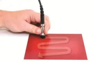
Using Scanning Technology to Acquire Higher Volumes of Data
Several manufacturers of electronic coating thickness gages have incorporated “scanning probe” technology and the associated support software into the data acquisition process. This newer technology enables the gage operator to obtain large sets of coating thickness data in a relatively short time frame. For example, coating thickness data was obtained by a certified coatings inspector on an actual bridge recoating project that included 12 batches of readings (nearly 600 readings) in just under 8 minutes (measurement time only) on bridge girders across four panel points. So it may be possible to obtain a more representative sampling of the coated area without impeding production. However, there are concerns with acquiring such large data sets, such as management of the data, handling outliers, determining the statistical significance of the data (i.e., what is an acceptable standard deviation or coefficient of variation), applicability of the Coating Thickness Restriction Levels 1-5 in SSPC-PA 2), etc. The scanning probe set-up on the gage itself is relatively easy to perform, and the software is capable of handling the large volume of data coming into the gages.
The SSPC Committee on Dry Film Thickness Measurement may consider adding a 10th non-mandatory appendix to SSPC-PA 2 to give the specifier the option of acquiring a much larger data set of coating thickness measurements without impeding production. In this manner, an owner may gain greater confidence regarding the uniformity and consistency of the applied coating film.